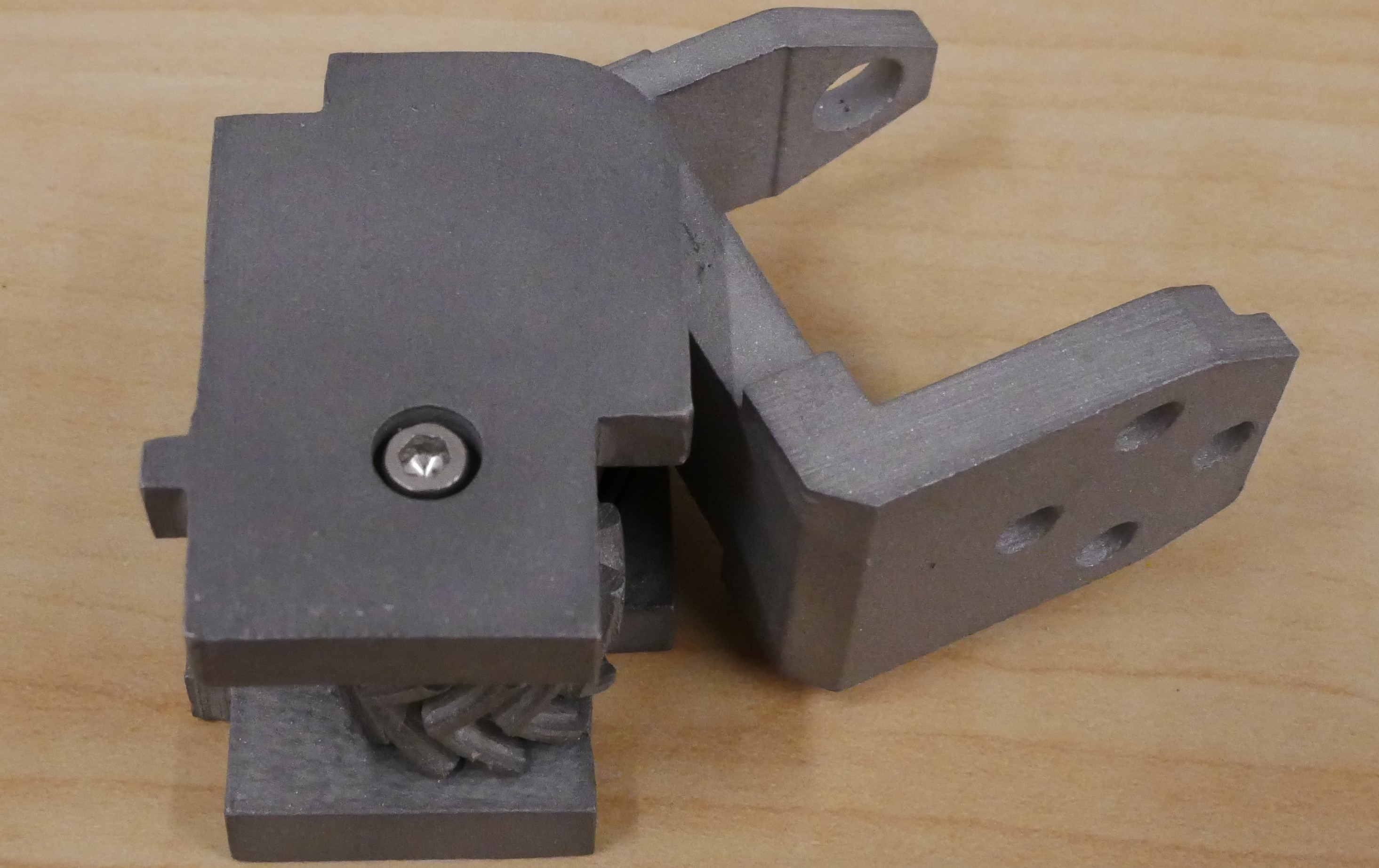
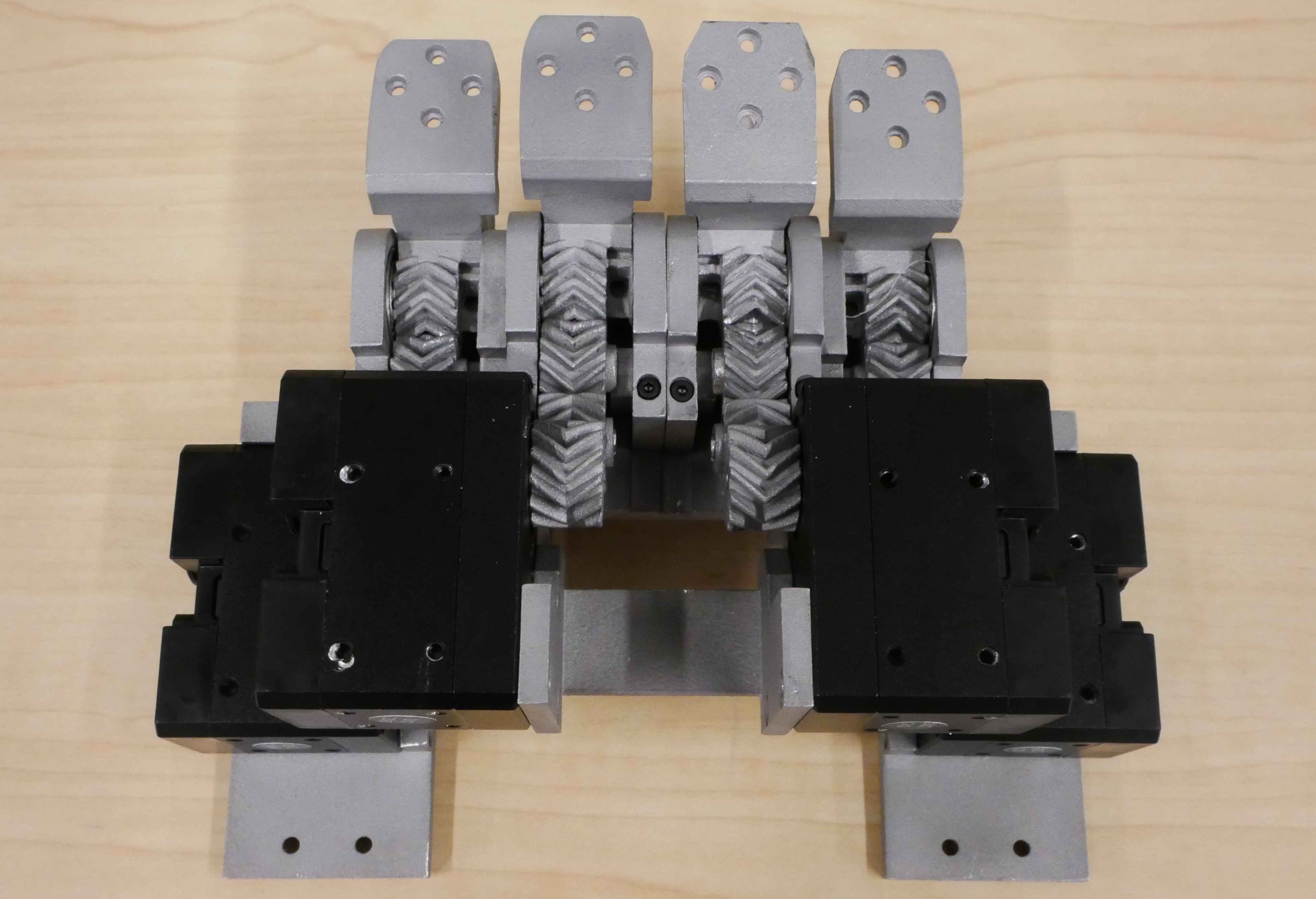
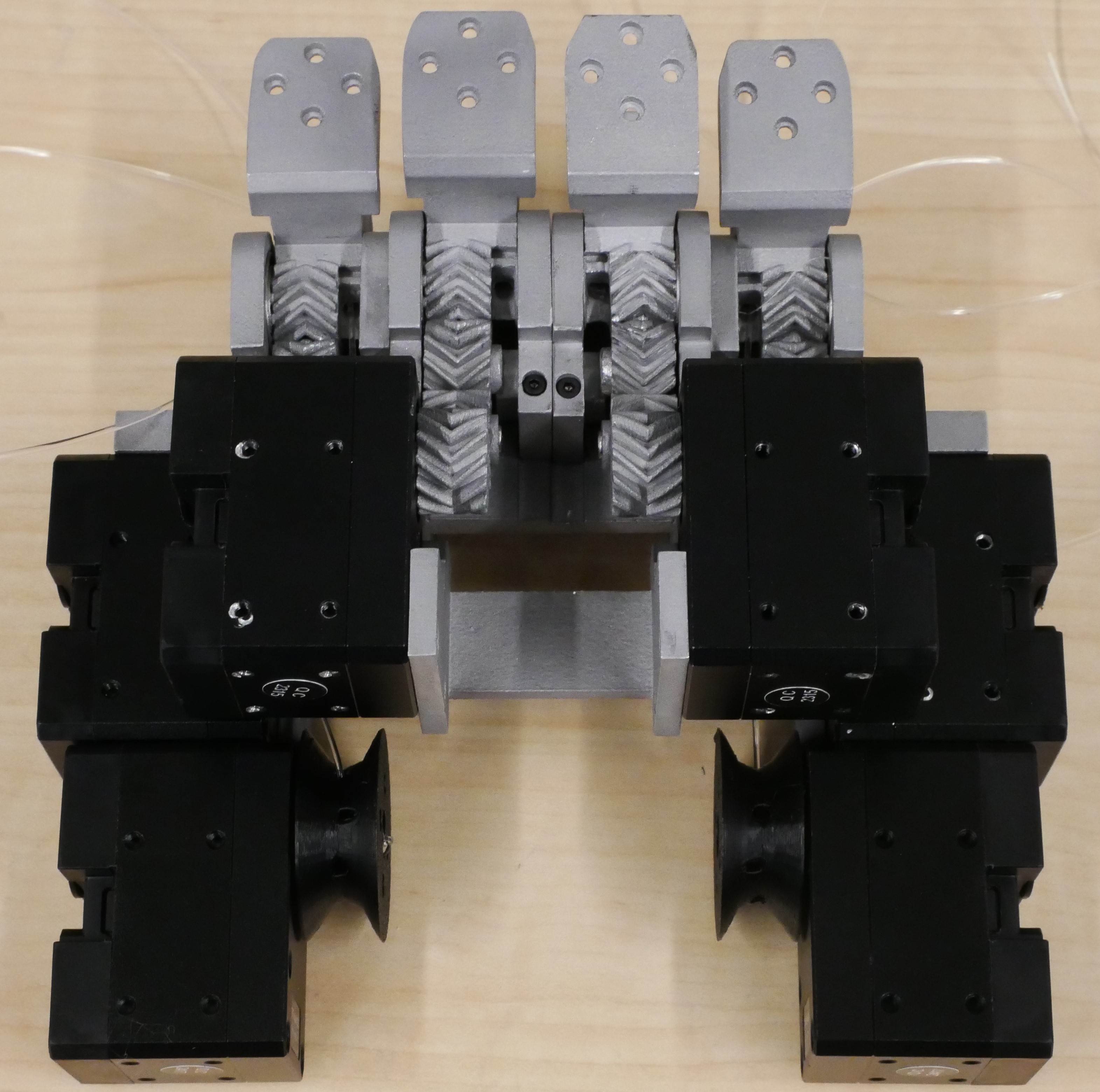
MCP Base Holders
- Insert one bearing into each of the MCP Holder Inners and Outers. If insertion is difficult, use a clamp to push them in. Ensure the bearings sit flush within their slots.
- Match pairs of MCP Holder Inner and Outers. Ensure both are either unmirrored or mirrored, so they connect face to face with the cutouts on the same side.
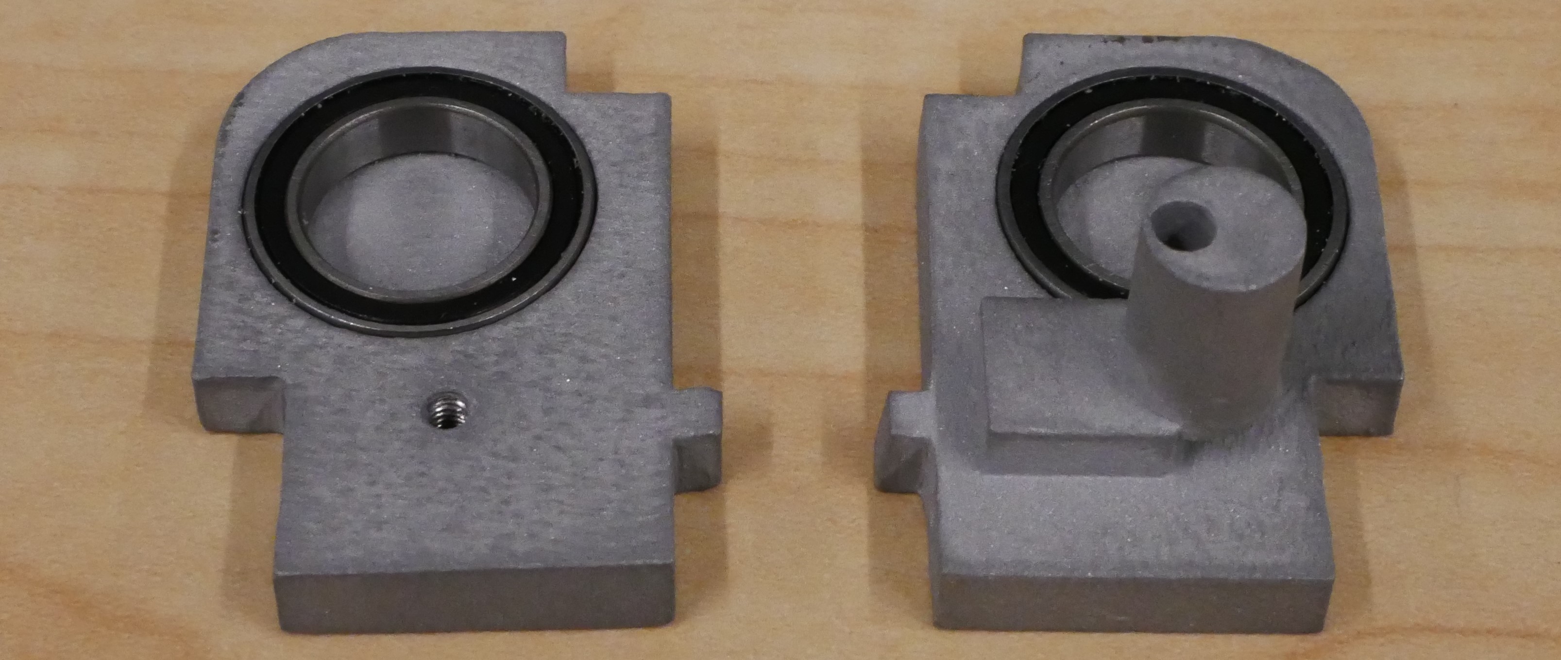
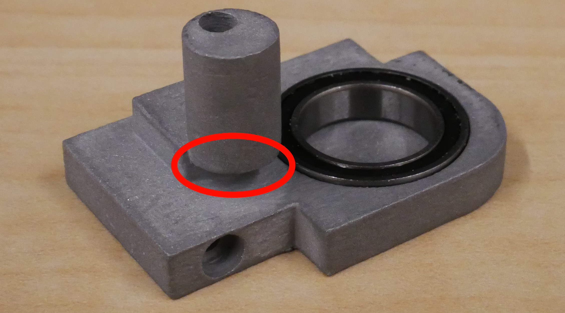
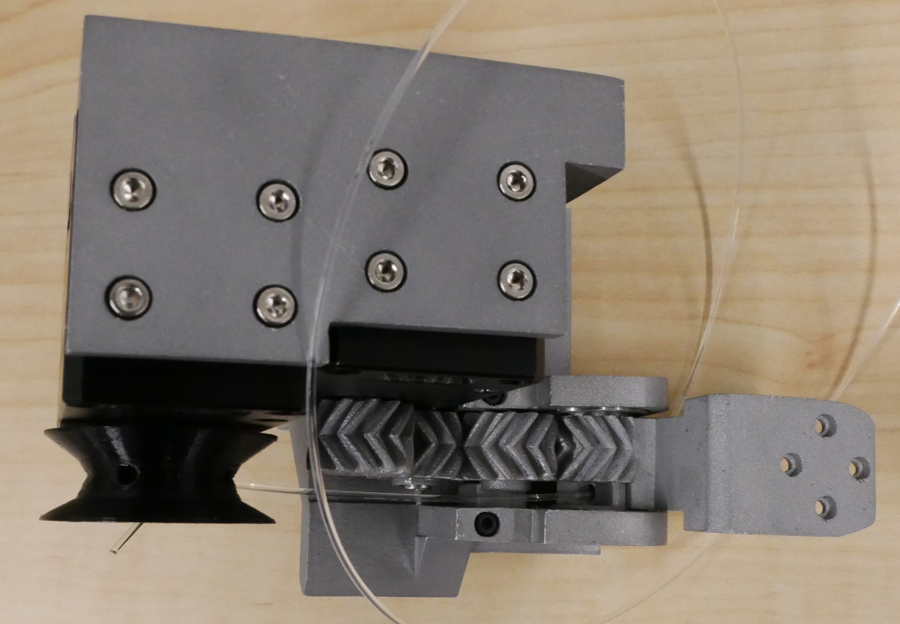
- The MCP Holder Inner has an axle sticking out of it where a gear will be placed. Note that this axle also has a tendon channel cut vertically near its base.
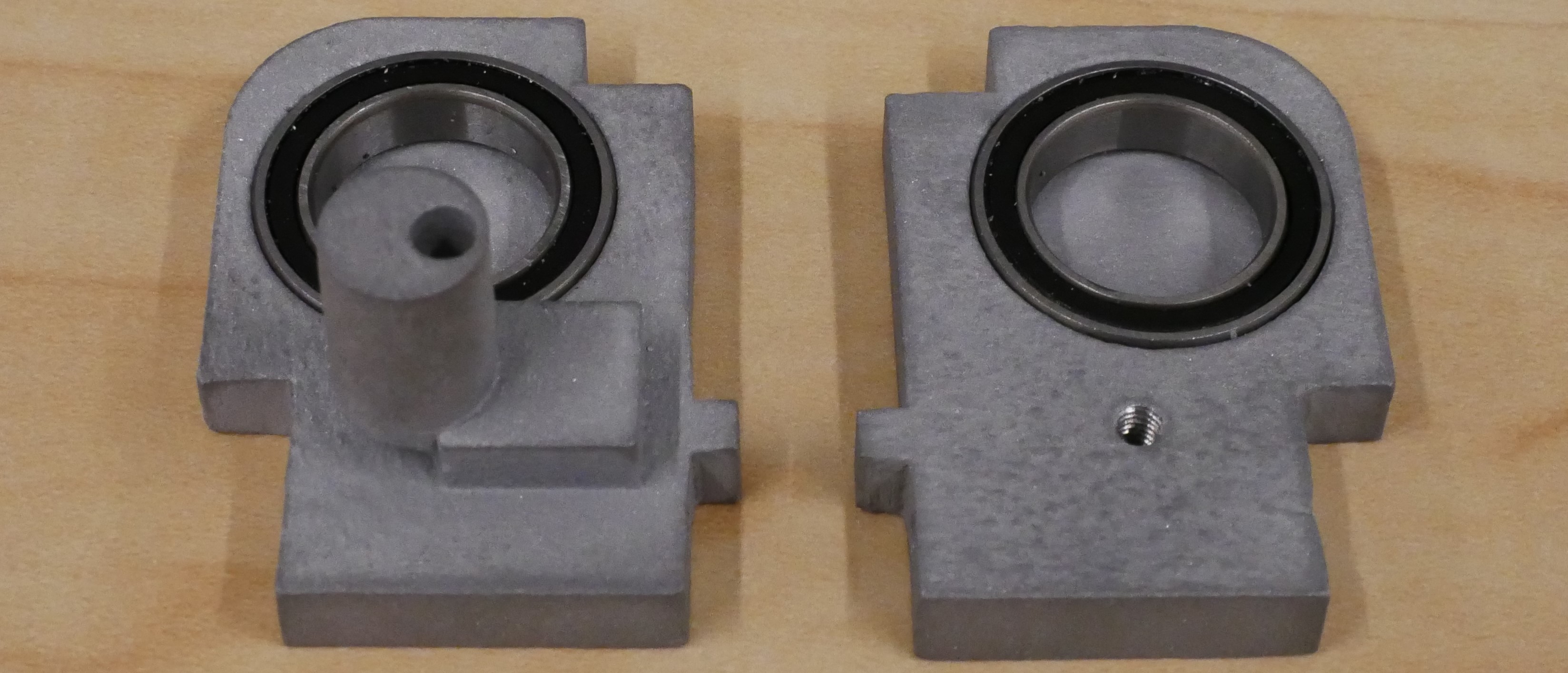
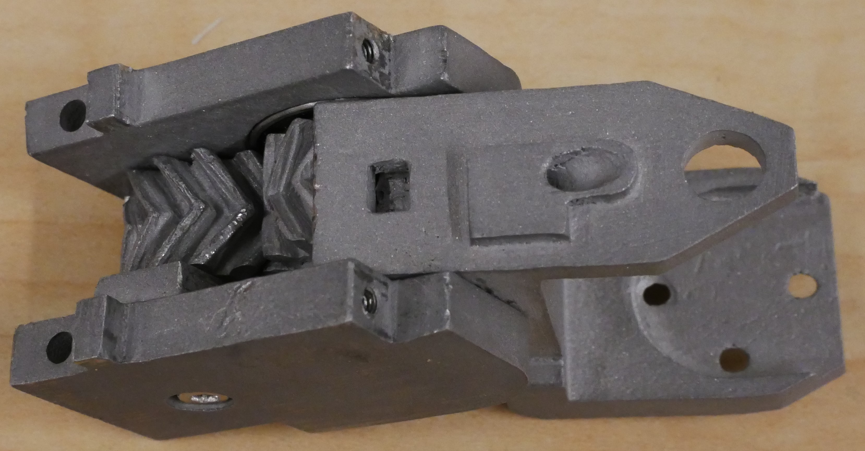
- Find an MCP Forward and locate the tendon hole. This hole is on the side without the gear and passes all the way to the top.
- When positioning the MCP Forward inside, make sure the tendon hole lines up with the MCP Forward Axle's tendon channel. If it does not, then find another MCP forward that matches this orientation.
- Find an Axle Gear. All Axle Gears are identical, with no mirrored versions, and feature a hole that goes all the way through.
- Test fit the MCP Forward between the MCP Holder bearings while sliding the Axle Gear onto the axle. If the gears do not mesh properly, flip the Axle Gear around until they do.
Tip: Double-check the orientation the parts to ensure correct alignment!
- Insert the MCP Forward into the bearings of each MCP Holder while simultaneously sliding the Axle Gear onto the axle.
- Make sure this presses down firmly all the way, you may need to use a clamp around it to press it down tight.
- Once it's tight, secure the MCP Base Assembly by fastening an M2.5 20mm bolt through the axle.
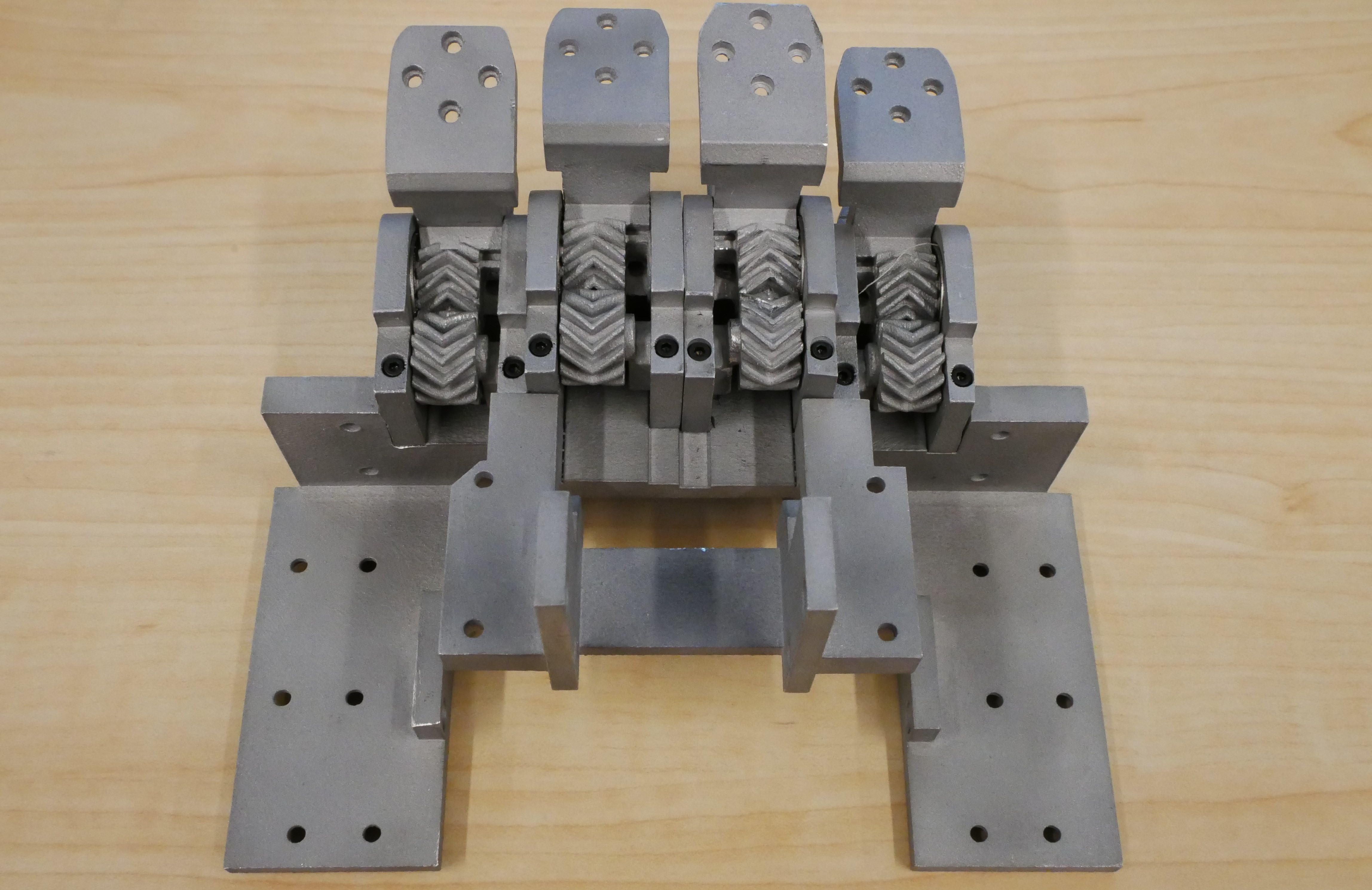
- Repeat this process five times to create three assemblies of one orientation and two of the mirrored orientation. Ensure that the thumb also has one correctly oriented assembly.
- If your parts were purchased from PCBWay, you will have an extra set of MCP Holder assemblies (three of each orientation). This redundancy is to prevent potential issues caused by incorrect parts being provided.
Tip: Double-check the orientation the parts to ensure correct alignment!
Once you have assembled the MCP Holder Assemblies, follow these steps to integrate them into the palm structures:
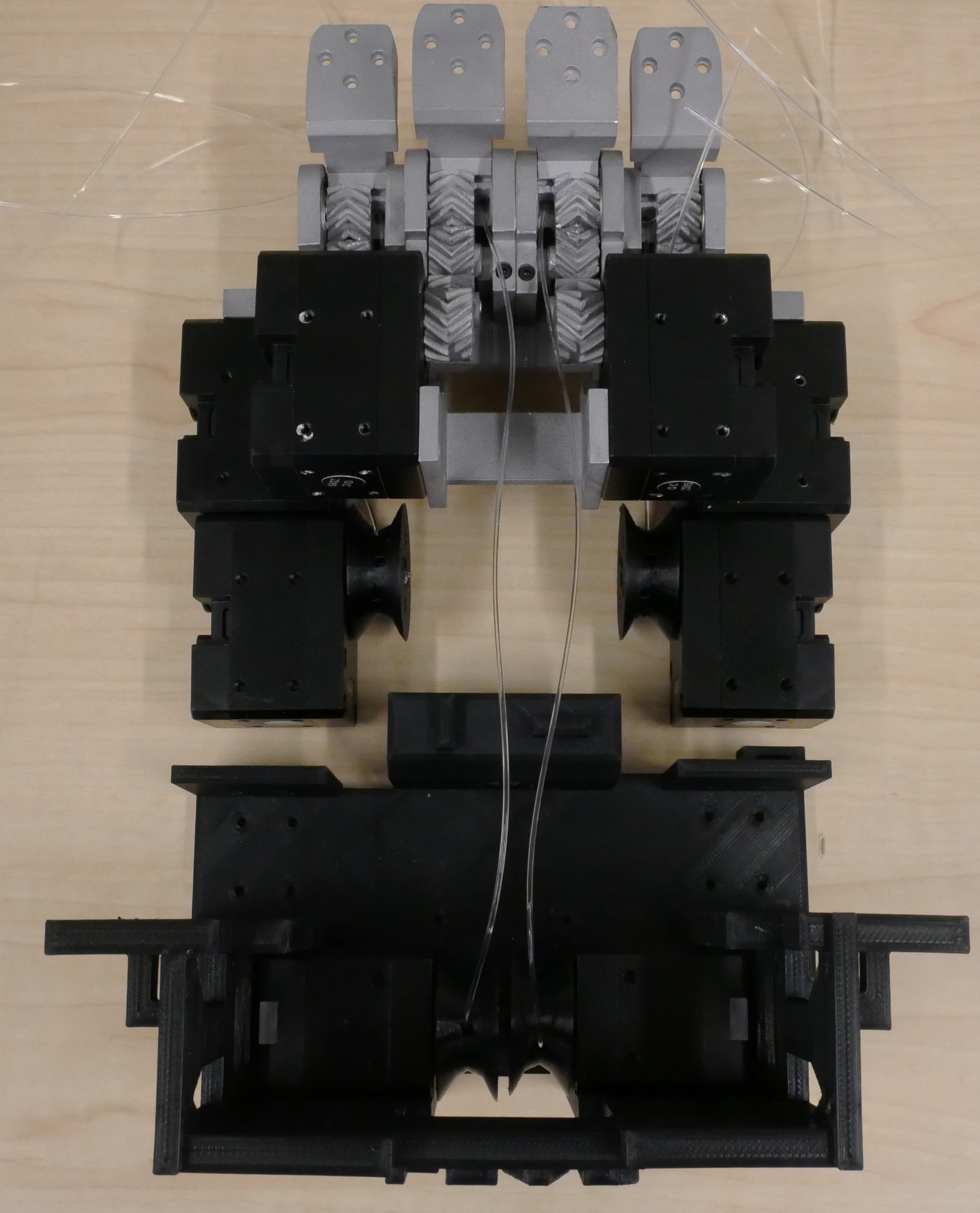
Fingers Lower Palm Integration
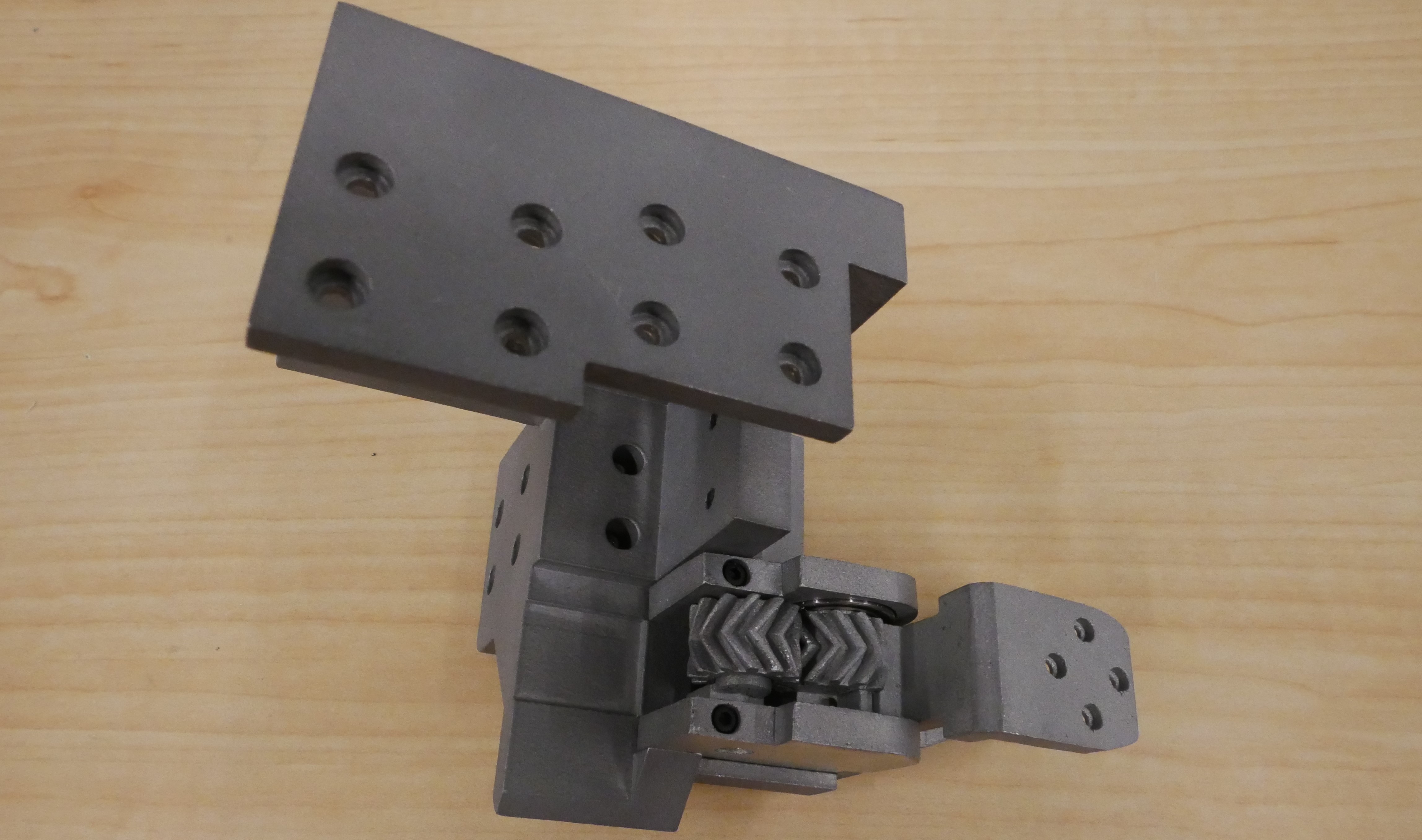
- Locate the 4 Fingers Lower Palm and one of the MCP Holder assemblies. Ensure the tendon channel on the MCP Holder is positioned towards the inside the palm, with the geared part facing towrads the outside.
- Test fit the MCP Holder assembly into the top section of the 4 Fingers Lower Palm. If it doesn't fit due to manufacturing tolerances, use a file or sandpaper to adjust the fit.
-
Secure the MCP Holder to the palm using:
- Two 20mm bolts from the bottom, passing through the MCP Holders and into the 4 Fingers Lower Palm.
- Two M2 6mm screw from the top, fastening through the palm's jut-outs into the MCP Holder. Note: Ensure these are 6mm screws, longer screws will damage the parts.
- Complete the process for all four MCP Holder assemblies, integrating them into the 4 Fingers Lower Palm.
Thumb Lower Palm Integration
- For the Thumb Lower Palm, ensure the geared part of the MCP Holder assembly faces the side of the motor mounts. The tendon channel should be positioned away from those motor mounts.
- Follow the same process as with the fingers, ensuring proper alignment and using the same screws.
Tip: Double-check the orientation the parts to ensure correct alignment!
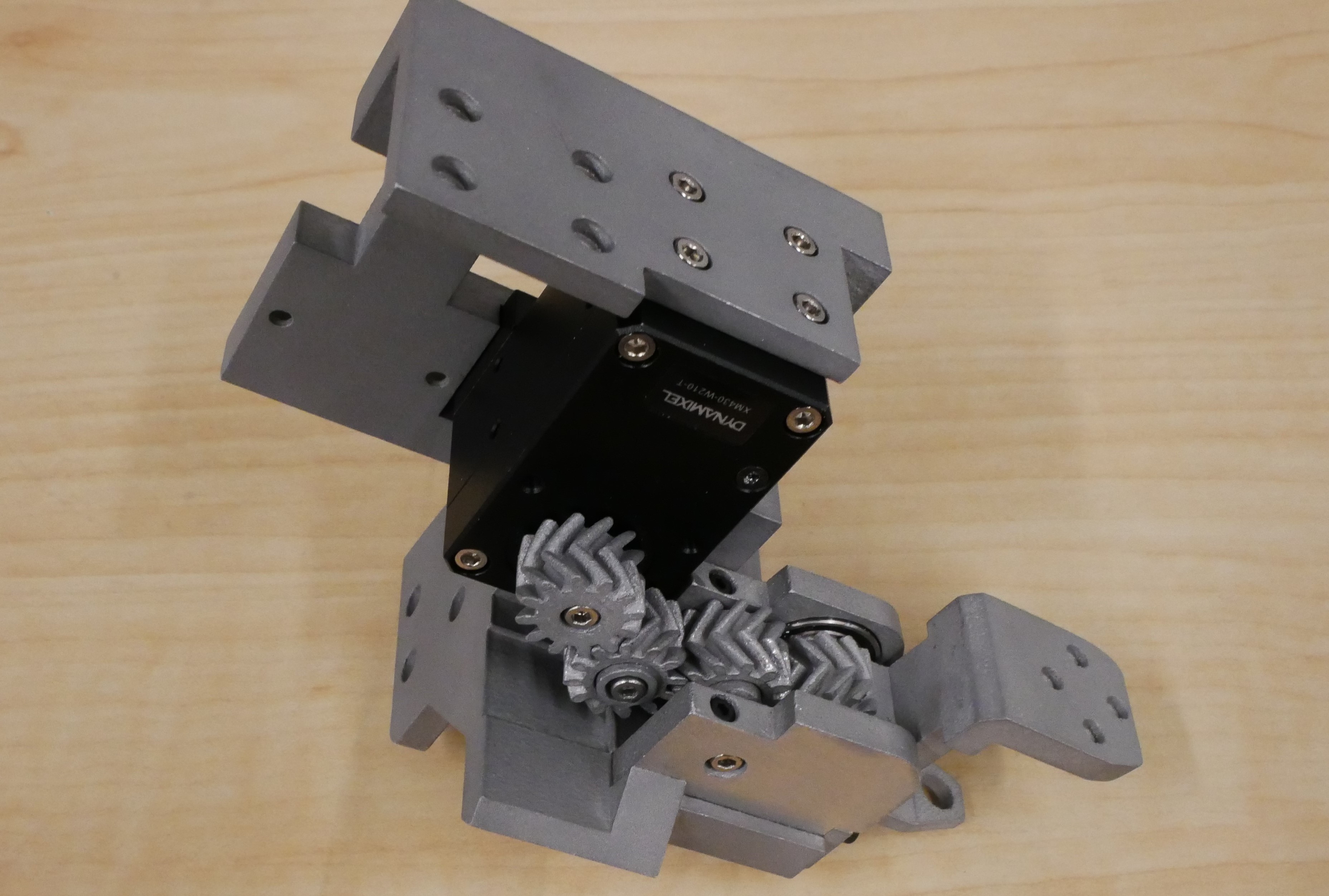
MCP Motors and Gears
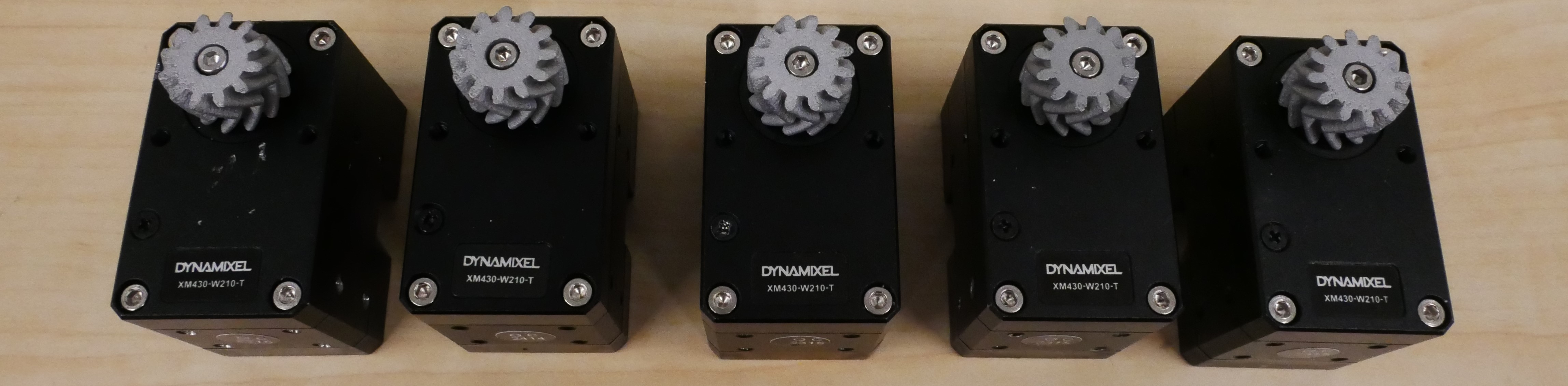
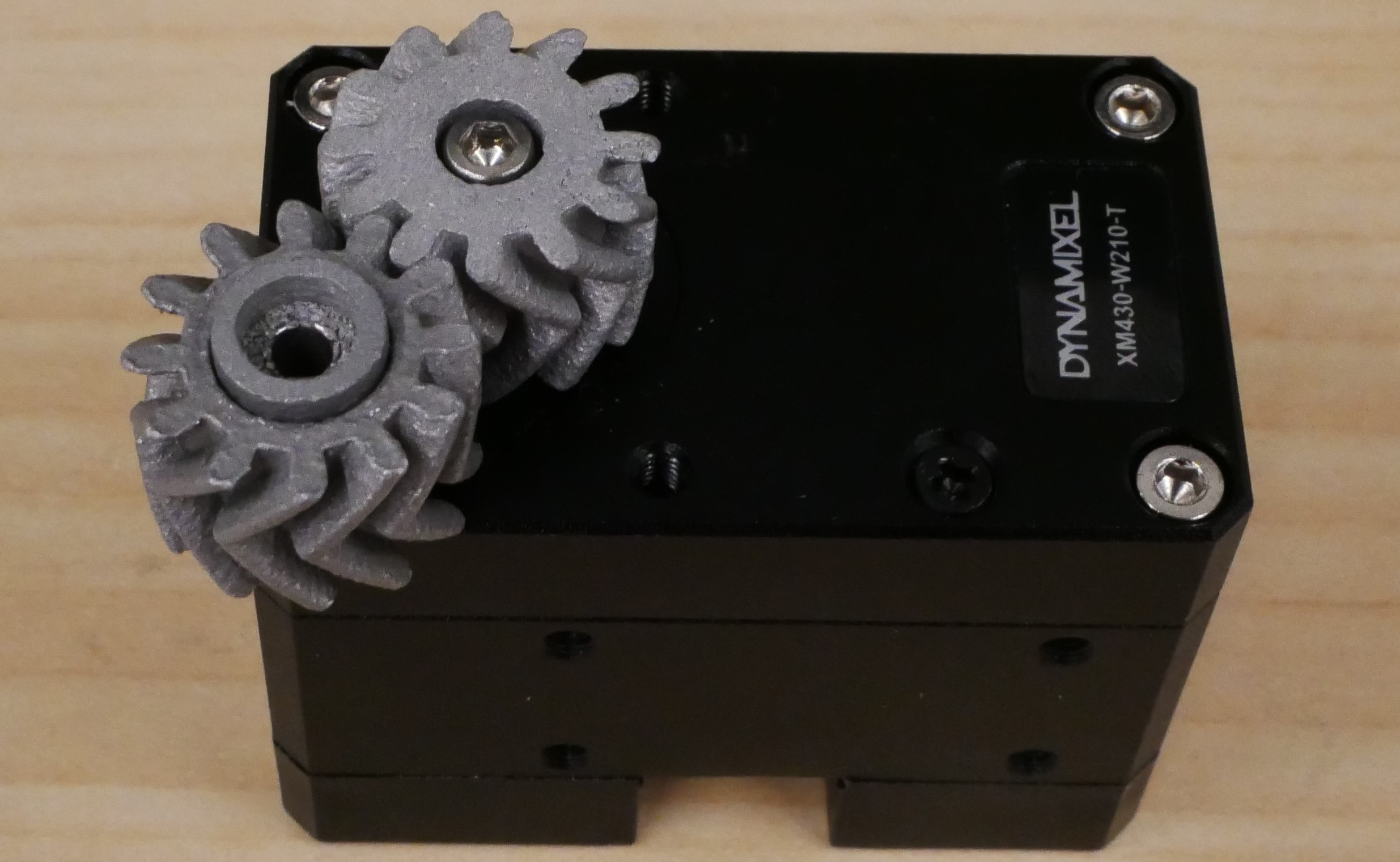
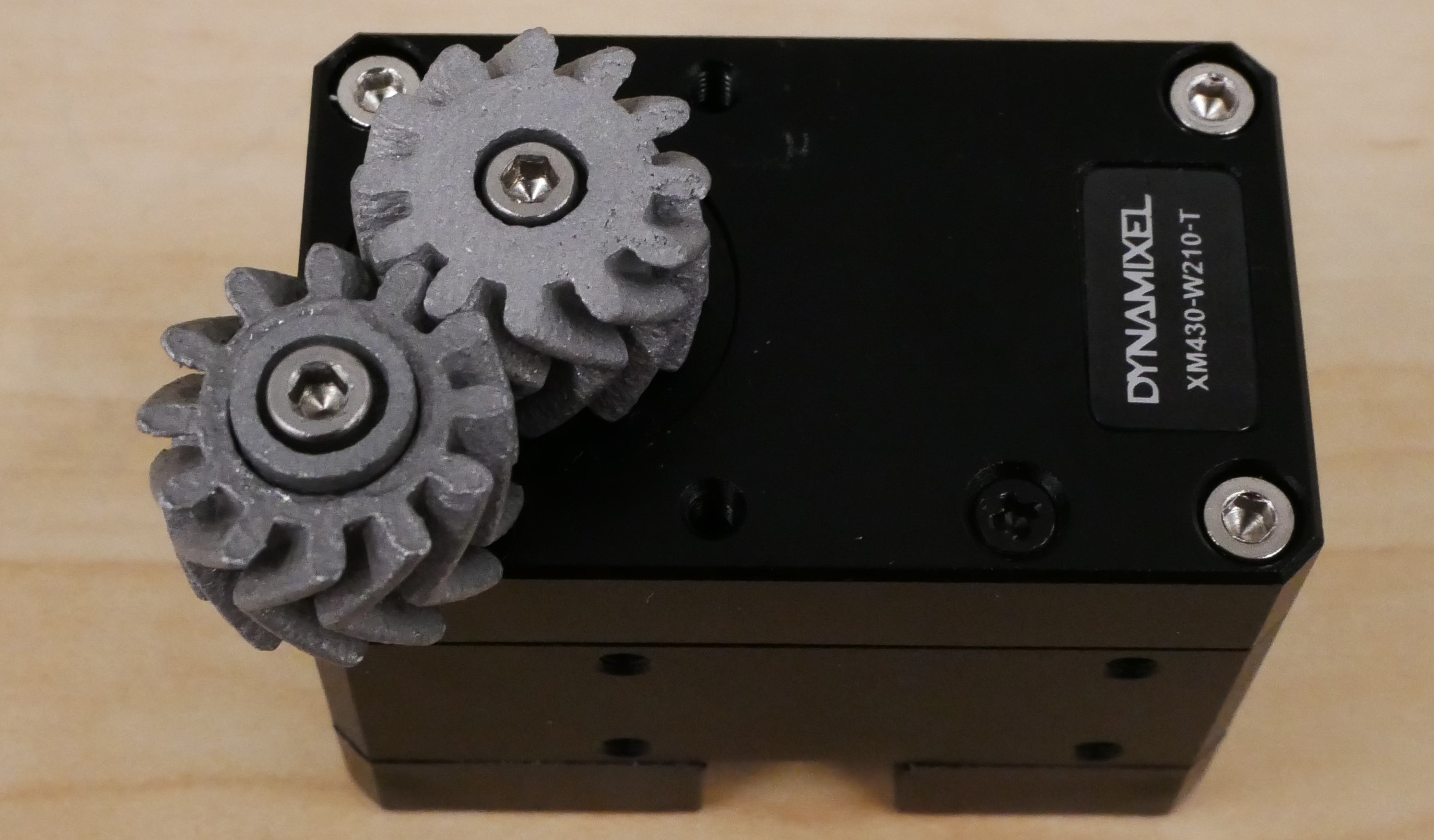
- Locate five XM430-W210-Ts and five horn gears.
- The Horn Gear should go on the motor horn of the XM430. Fasten three of the normal orientation and two of the mirrored gears onto the horn using M2.5 10mm screws.
- Focus on the index finger first. Locate its position on the 4-Finger Lower Palm. The XM430 motor will have the the horn gear facing inward, oriented towards the center.
- Next, find a Screw Gear and a Screw Bushing.
- The Screw Gear and Screw Bushing will replace the M2.5 screw in the XM430 motor corner that is towards the front of the hand.
- Test fit the Screw Gear onto the Axle Gear on the 4-Finger Lower Palm. If it meshes, great! If not, swap it for a mirrored Horn Gear and a Mirrored Screw Gear, then try again. Note: The correct gear may not spin smoothly but should still fit properly.
- Once you find the right screw gear, position the XM430 motor with the horn gear facing towards the center of the 4-Finger Palm.
Great, the parts are setup. The next step will explain how to screw the components together.
Once you verify the 4 gears are meshing, it is time to fasten them.
- First remove the m2.5 screw facing towards the front of the hand in the top corner of the Dynamixel XM430.
- Stack the screw bushing, screw gear together on top of the corner of the Dynamixel. Add some grease between the screw bushing and screw gear.
- Screw it down very tightly with a M2.5 22m screw and importantly apply some Red Locktite.
- Use 6 M2.5 4mm bolts and fasten the motor to the four fingers lower palm.
- Next, repeat the steps for the pinky finger. Replace the front corner M2.5 screw on the motor with the Screw Gear and Screw Bushing as before.
- Now, repeat the process for the middle and ring fingers. Replace the back corner M2.5 screw on each motor with the Screw Gear and Screw Bushing.
- Each middle and ring finger motor should be fastened with two M2.5 4mm or 6mm bolts. Optionally, you can also remove the bottom two M2.5 bolts from the Dynamixel Motor. You can refasten with m2.5 16mm bolts through the 4-Finger Lower Palm Plate holes.
- The thumb motor should be fastened with six M2.5 4mm bolts. Optionally, you can also remove the back four M2.5 bolts from the Dynamixel Motor and refasten them and secure the thumb lower palm plate through it.
Tip: All the gears should fit in tightly. If they don't spin freely that's okay, we will fix that in the next step.
- Ensure all four M2 screws are tightly secured in the MCP forward assemblies, and the motors are fastened securely.
- Connect one of the MCP motors to a 12V power source, a U2D2, and the Dynamixel Wizard software on your computer.
- Use the software to scan for the motor and switch the motor to current control mode.
- Turn the torque on and move the MCP module forward and backward using the current control slider.
- If the motor doesn't move, try applying some pressure with your hands in the same direction as applied by the motor.
- Continue this process until the motor and joint spin more smoothly.
- Repeat these steps for the other four motors.
Tendons and Bottom Plate
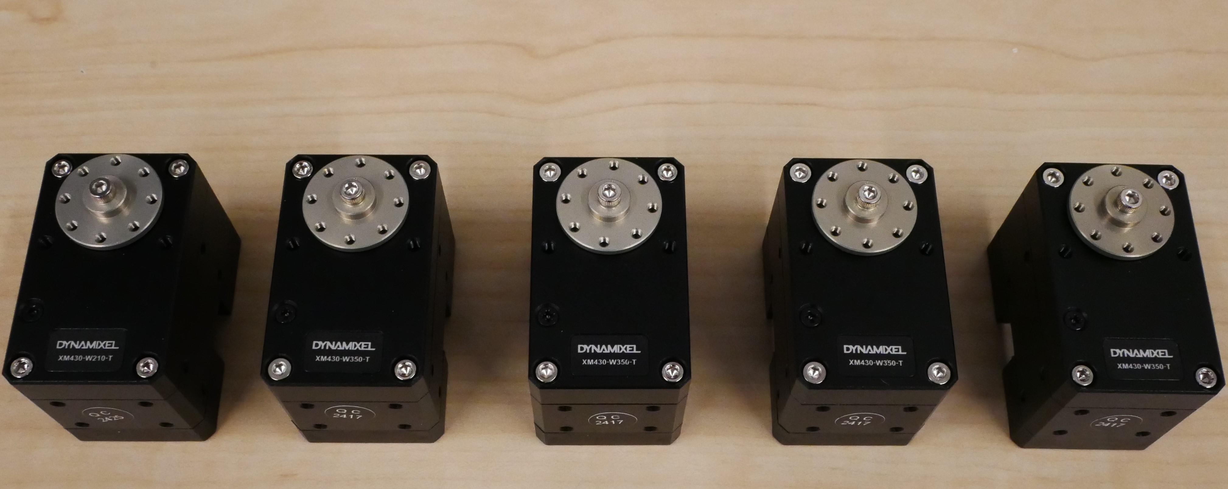
- Locate five XM430-W350-Ts and five of their thrust washers and horns.
- Use the included M2.5 6mm screw to fasten each of them onto the motors.
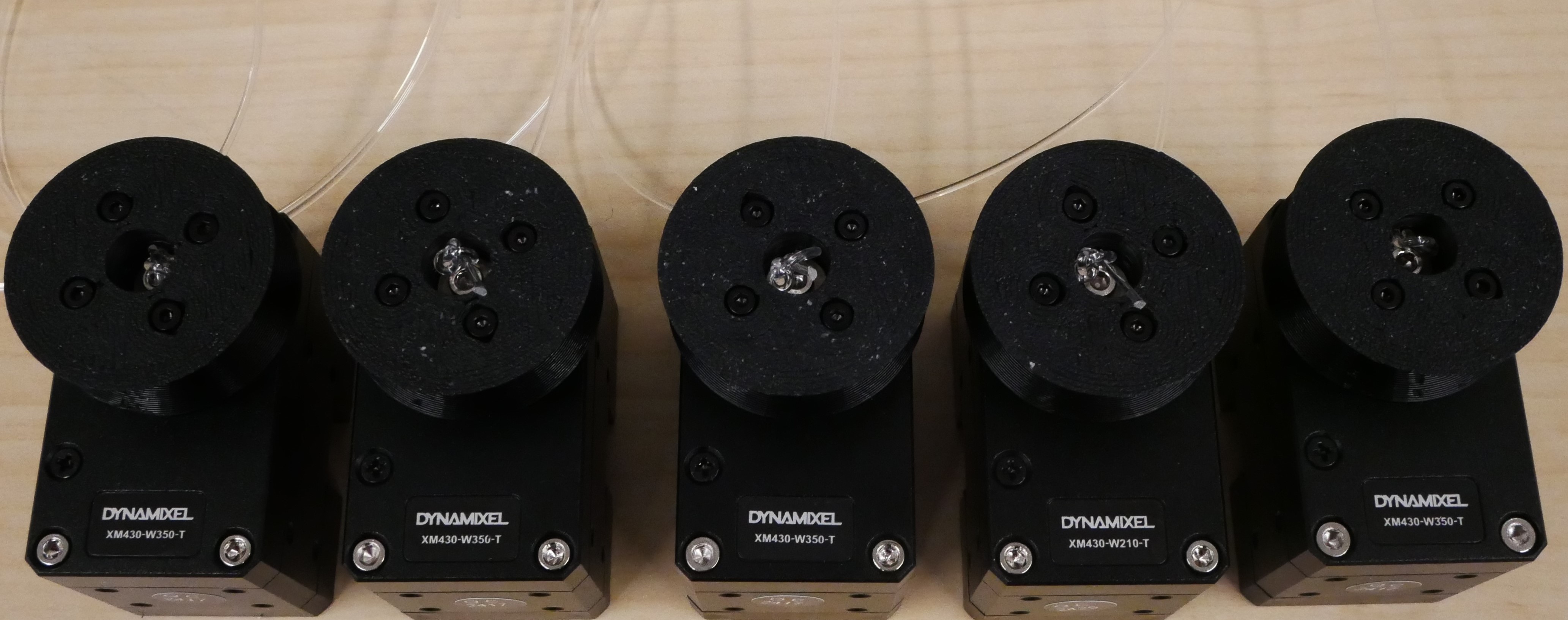
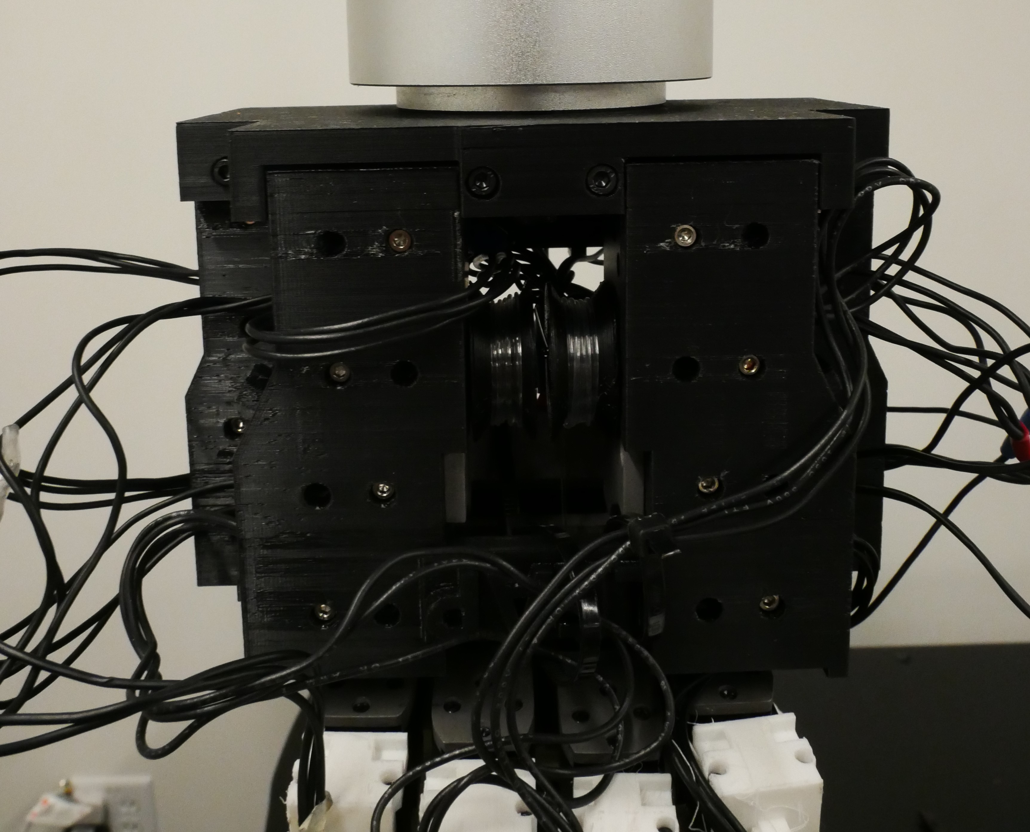
- Locate 5 pulleys.
- Cut 5 pieces of Berkley Trilene Big Game Monofilament Fishing Line (100lb, Clear, Mono Leader, 0.99 mm Diameter) roughly 60cm long each.
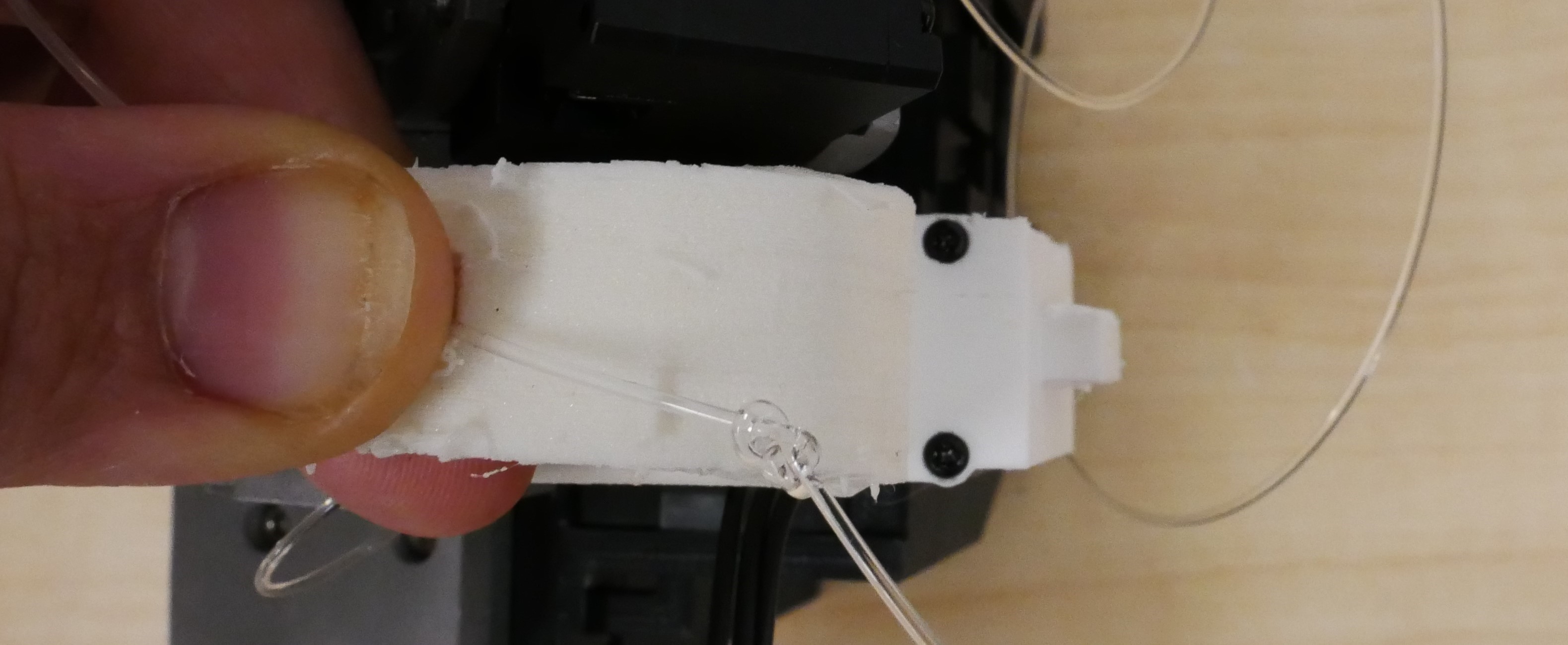
- Double Knot one side of the tendon. Feed the non-knotted end into the middle of the pulley though one of the four holes on the sides. The knot should be in the middle of the pulley.
- Pull the knot tight and ensure it doesn't pull through the hole. Cut the excess off the knot.
- Attach each pulley to each motor horn using 4 m2 10mm screws.
Lets start with the index finger motor:
- Locate one tendon, one motor, and the 4-Finger Assembly.
- Rotate the MCP Forward so it faces upward, and push the tendon through the bottom hole of the MCP Forward module.
- Pull the tendon through as it emerges from the top of the MCP Forward module.
- Find the tendon channel on the MCP Holder and push the tendon into it. This ensures the tendon does not get caught in the MCP gears.
- Loosely secure the motor to the 4-Finger Lower Palm using two M2.5 screws.
Now, let's move on to the pinky finger and thumb:
- Do the same exact thing for the pinky finger.
- For the thumb, insert the thumb tendon through the MCP Forward like usual. Secure the thumb curl motor using four M2.5 4mm screws. Optionally, remove the back four M2.5 bolts from the Dynamixel Motor, refasten them, and attach them through the thumb lower palm plate for additional support.
Now, let's do the middle and ring fingers:
- Rotate the MCP Forward so it faces upward on these two motors and push the tendon through the bottom hole of the MCP Forward module as before.
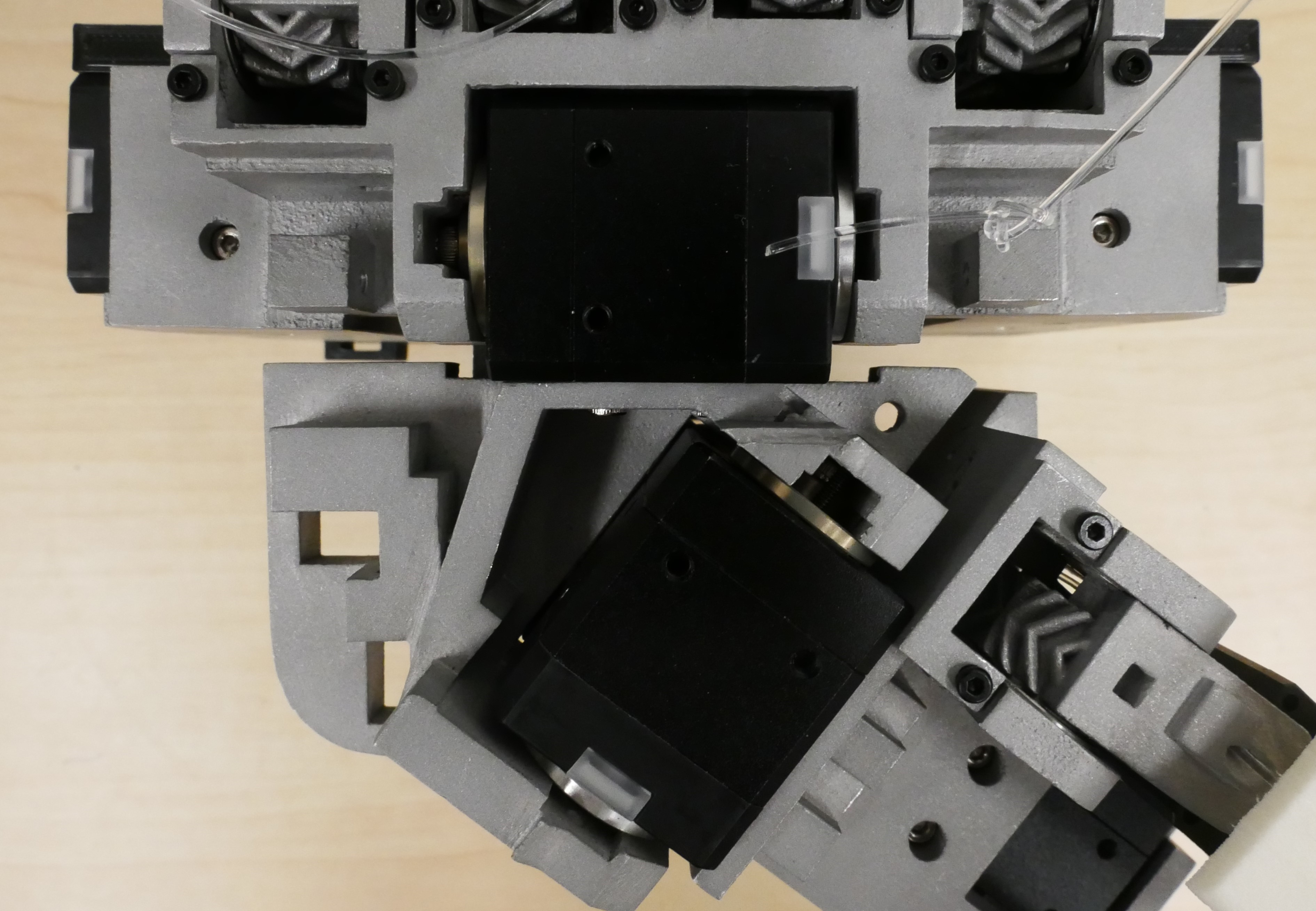
- These motors go underneath the MCP Forwards for their respective fingers but there is no place on the 4-Finger Lower Palm to secure these motors.
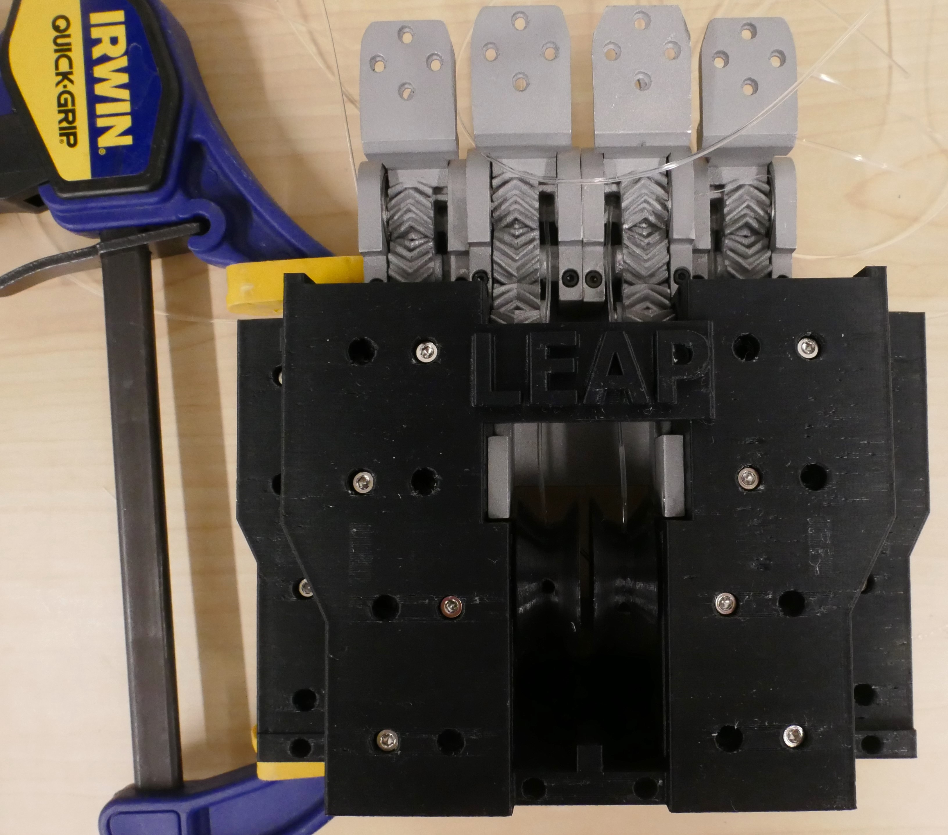
- Instead, locate the 4 Fingers Bottom.
- Place these motors into their respective slots in the front of 4 Fingers Bottom with the pulleys facing towards the center of the hand.
Tip: If the tendon has difficulty passing through the MCP hole, you can use a long, flexible drill bit—such as those designed for clearing 3D printer nozzles or heat breaks—to deburr the channel.
Finally, fasten 4 Fingers Bottom:
- Pull all the tendons through the top to ensure they are taut and not loose.
- Carefully slide the 4-Fingers Bottom, along with the two motors, up and over the other motors.
- Take care not to pinch any tendons during this step.
- Secure each motor using at least four M2.5 4mm screws, fastening them all the way around the hand. You do not need to use all of the screw holes necessarily.
- Ensure the tendons remain pulled through their respective holes and not caught in the gear teeth.
MCP Side and Fingers
Notes before we begin:
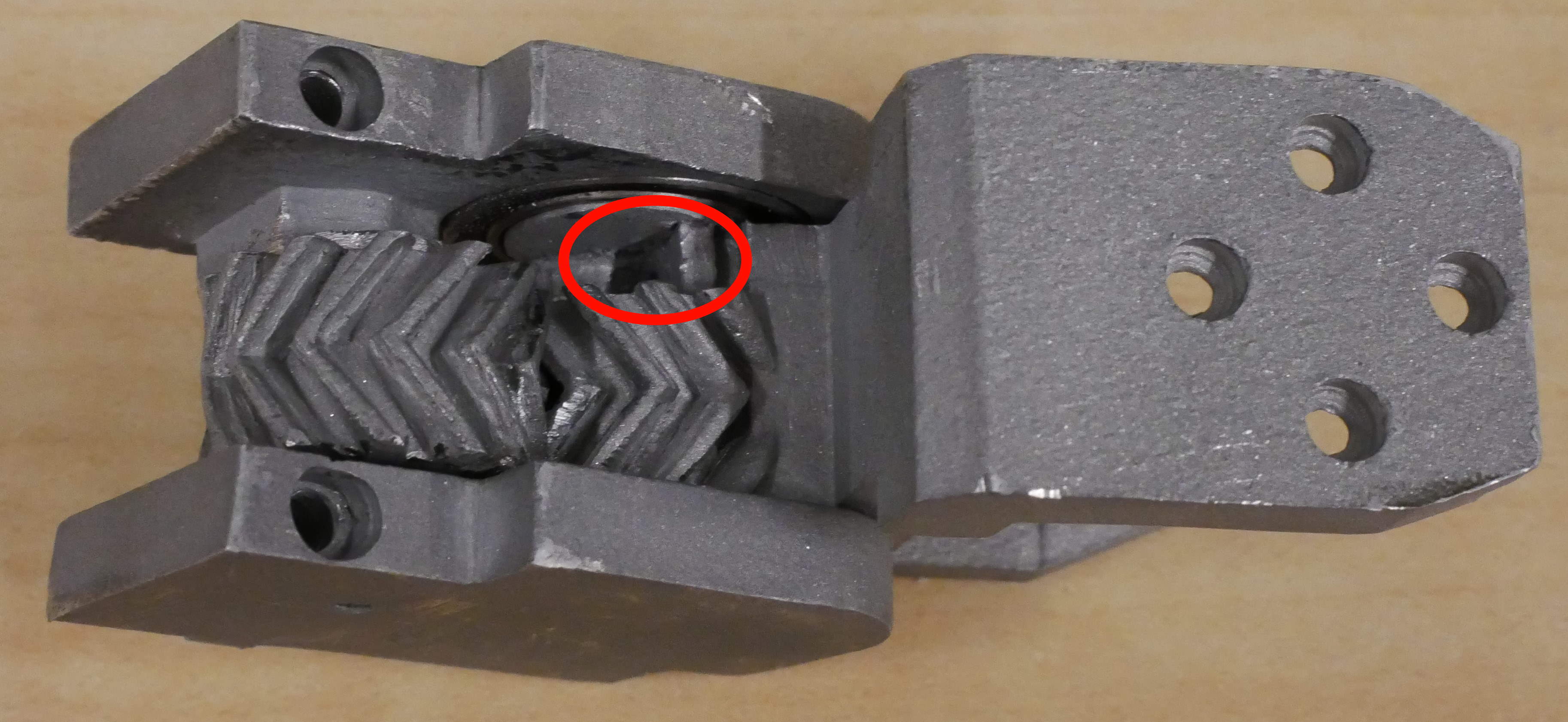
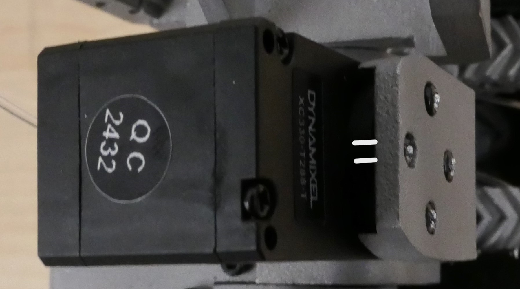
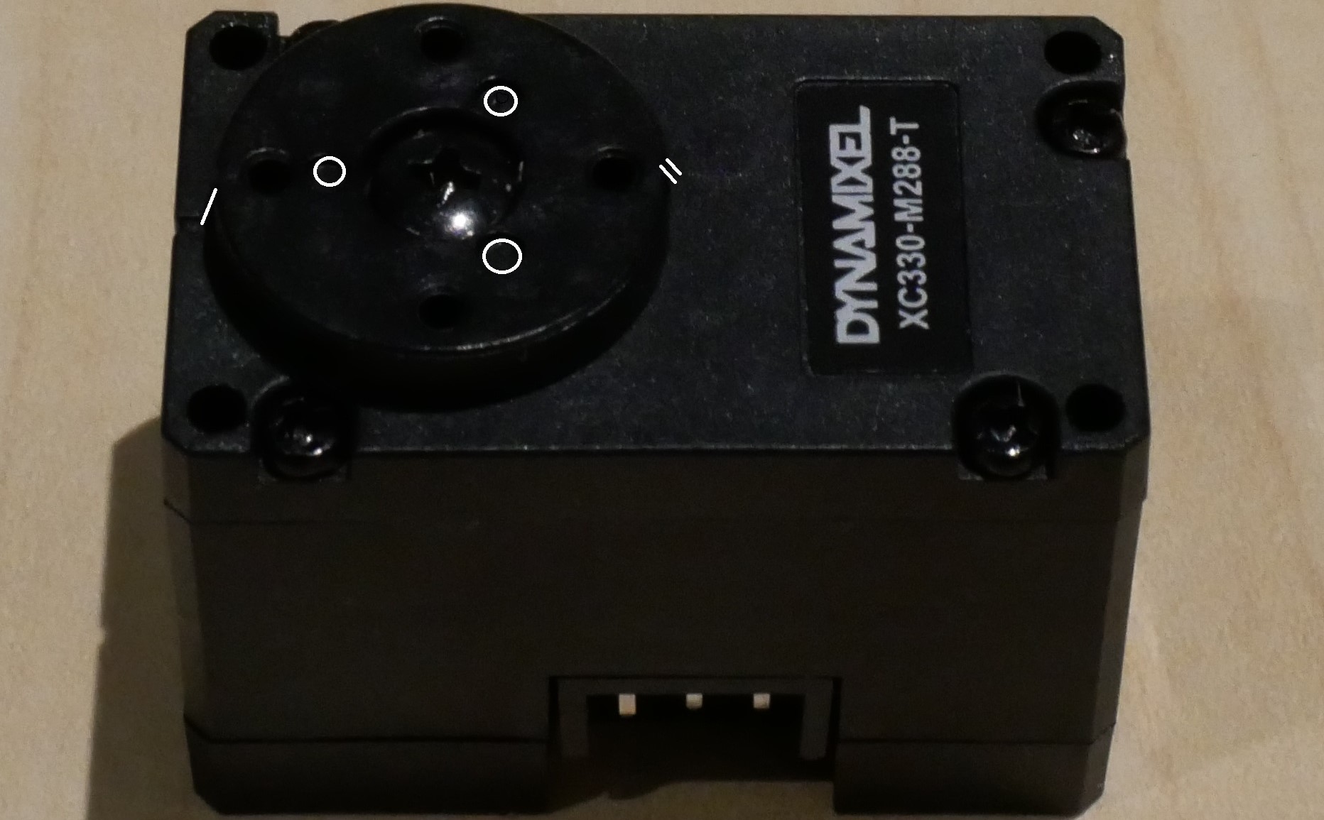 The dots and dashes I've outlined on the motor horn indicate the Home position for the Dynamixel XC330s. Most Dynamixels are shipped already oriented in this home position.
For proper MCP side assembly, ensure the motor horns stay in this home position when attaching.
The dots and dashes I've outlined on the motor horn indicate the Home position for the Dynamixel XC330s. Most Dynamixels are shipped already oriented in this home position.
For proper MCP side assembly, ensure the motor horns stay in this home position when attaching.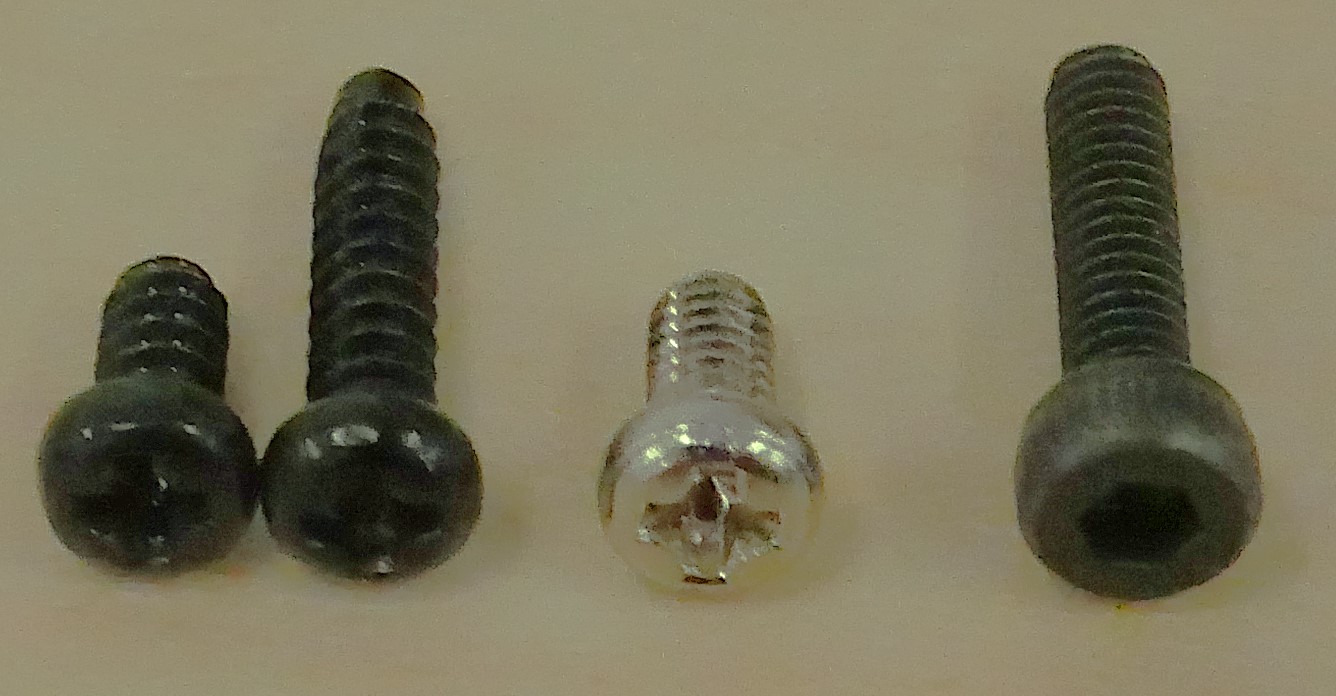 There are three distinct types of screws used in assembly:
TAP Screws (Left): These Phillips head screws have serrated edges and come included with the Dynamixel brackets
Standard Dynamixel M2x4mm (Middle): These are regular, non-TAP screws supplied by Dynamixel
Hex Head Screws (Right): These are standard hex-head screws
Note in the next few assembly steps where we refer to tap screws.
Now to assemble the motors:
- Locate the five XC330-T288-T motors and their accompanying screws.
- Ensure that the motor horns are in the "home" position, as shown in the image below.
- Carefully insert each motor into its designated slot on the five MCP Forwards.
- If the motor horn has shifted, realign it with the holes on the bottom in the right home pose.
- Secure each motor with the four M2 4mm TAP screws that come from Dyanmixel.
- Take the MCP Spacers and insert them into the holes at the top of the MCP Forwards.
- Fasten each spacer to the motor using an M2.6 6mm TAP screw. These screws are included with the FPX330-H101 Dynamixel set.
- Add a long Dynamixel cable to one of the connectors of each of the XC330 motors. This is easier to do before the fingers are placed on the motors.
Tip: If you're having trouble aligning the motor horn during insertion, you can power the motor in position mode while inserting it to keep the horn aligned.
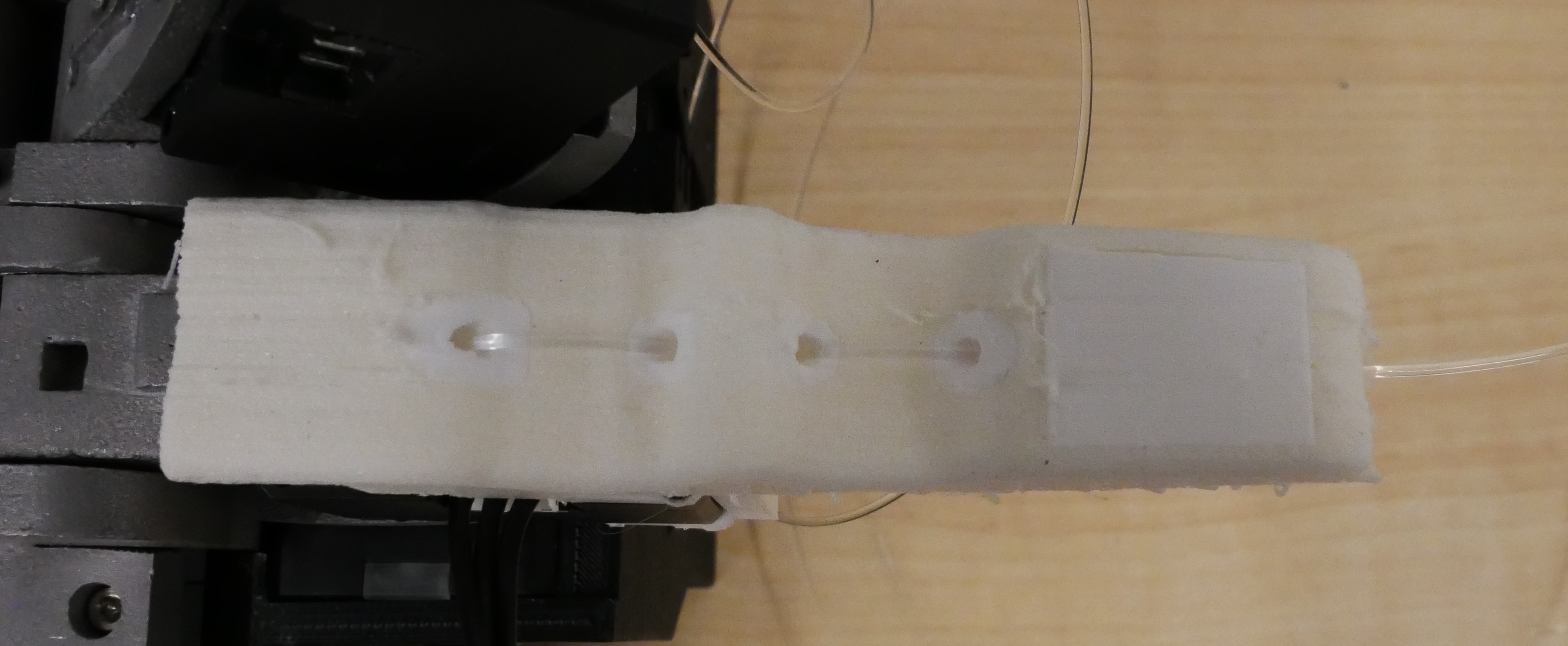
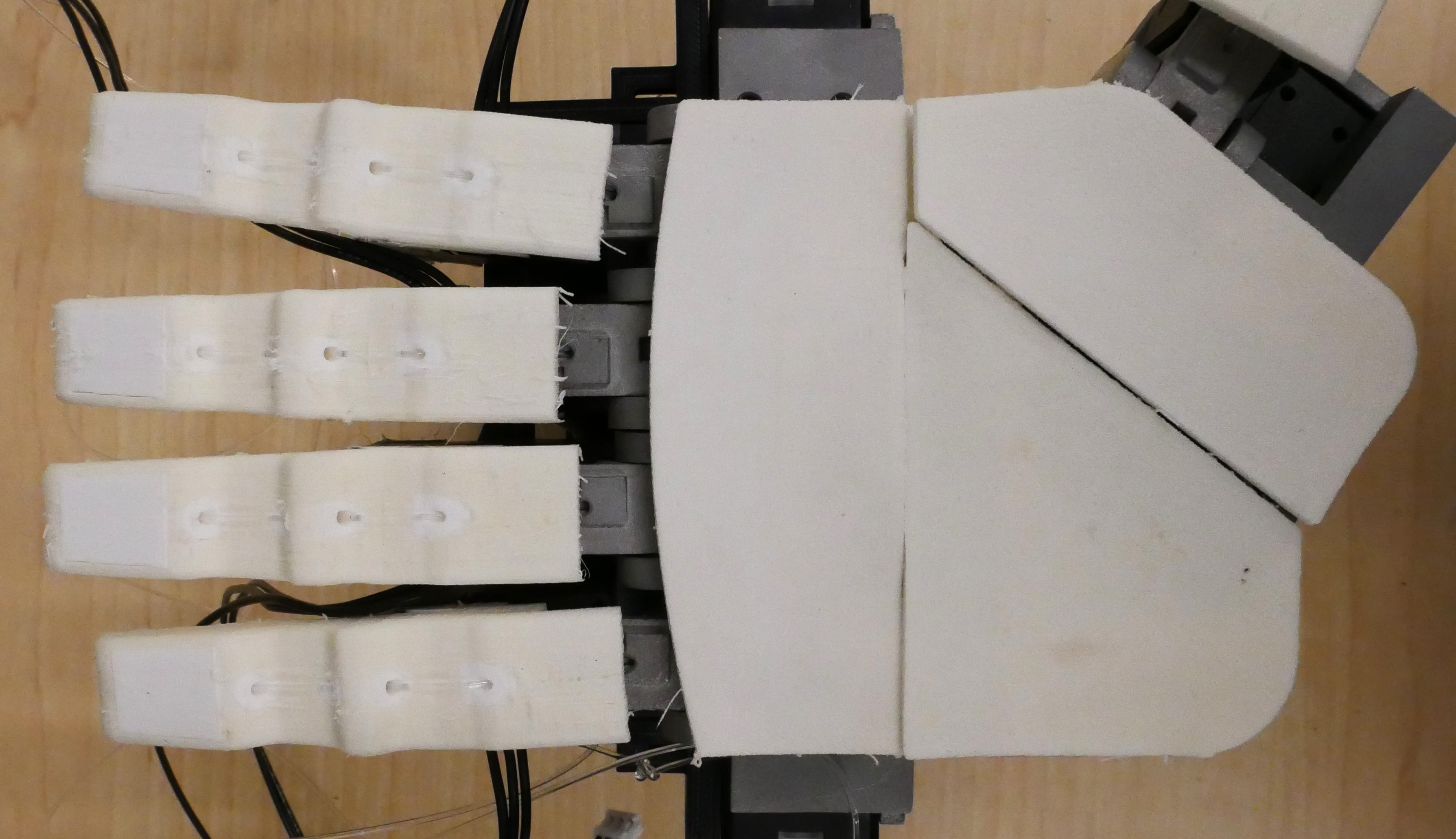
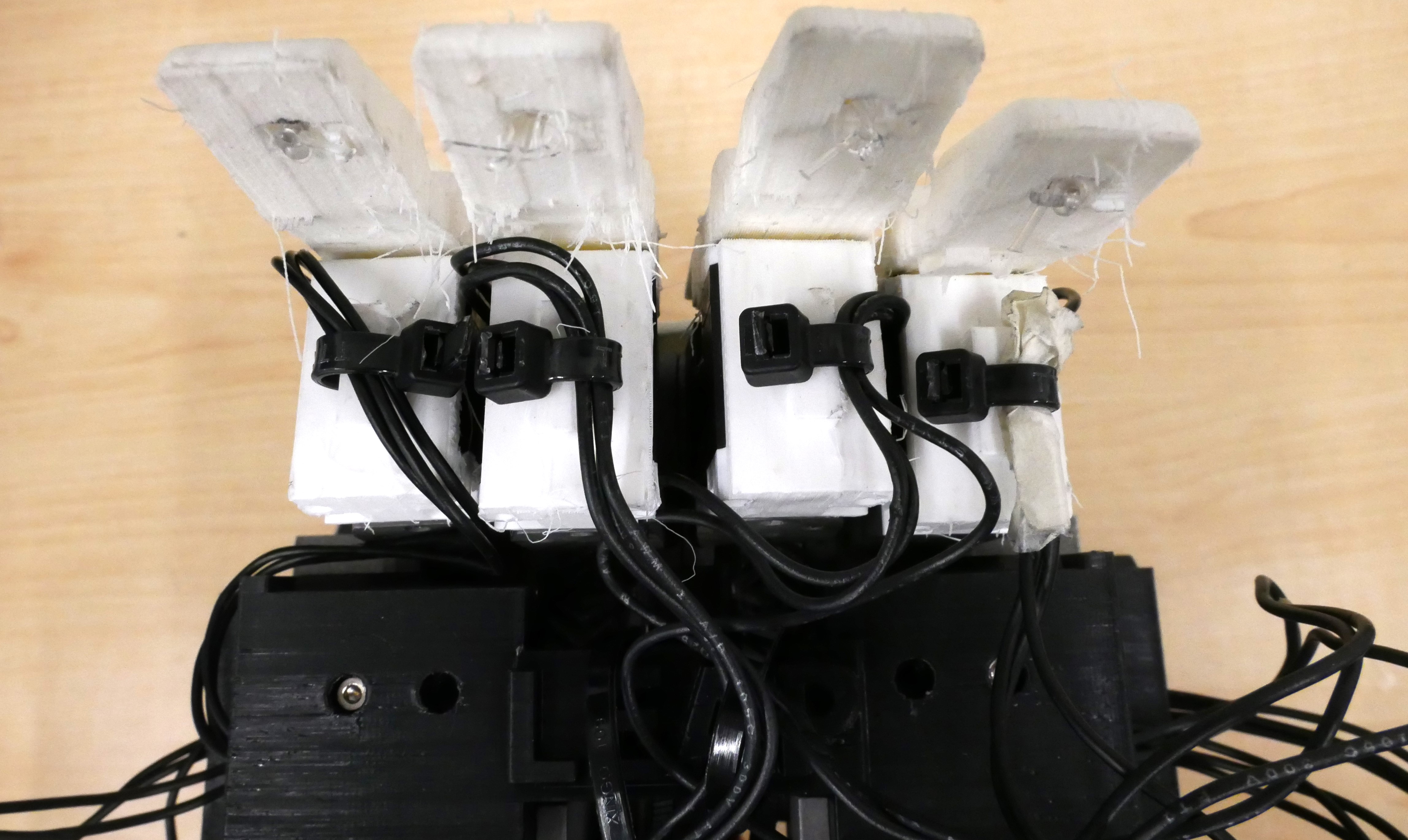
- Locate the 3D printed fingers and remove the support material by gently bending them back and forth and using a small cutter.
- Push the tendon through each of the center channel pieces of each finger. Tie a double knot at the end of the tendon and cut off the excess.
- Make sure one connector of the motor has a long 180mm cable connected to it.
- Push each finger FIRMLY onto the MCP Side motors so that the two holes on the top and two holes on the bottom of the motor line up.
- Use four M2 8mm TAP screws (comes with the motors and are black with phillips head) to attach each finger to each motor.
Tip: Make sure the fingers are FIRMLY pushed onto the XC330 motors before screwing them in so you do not damage the holes on the motors.
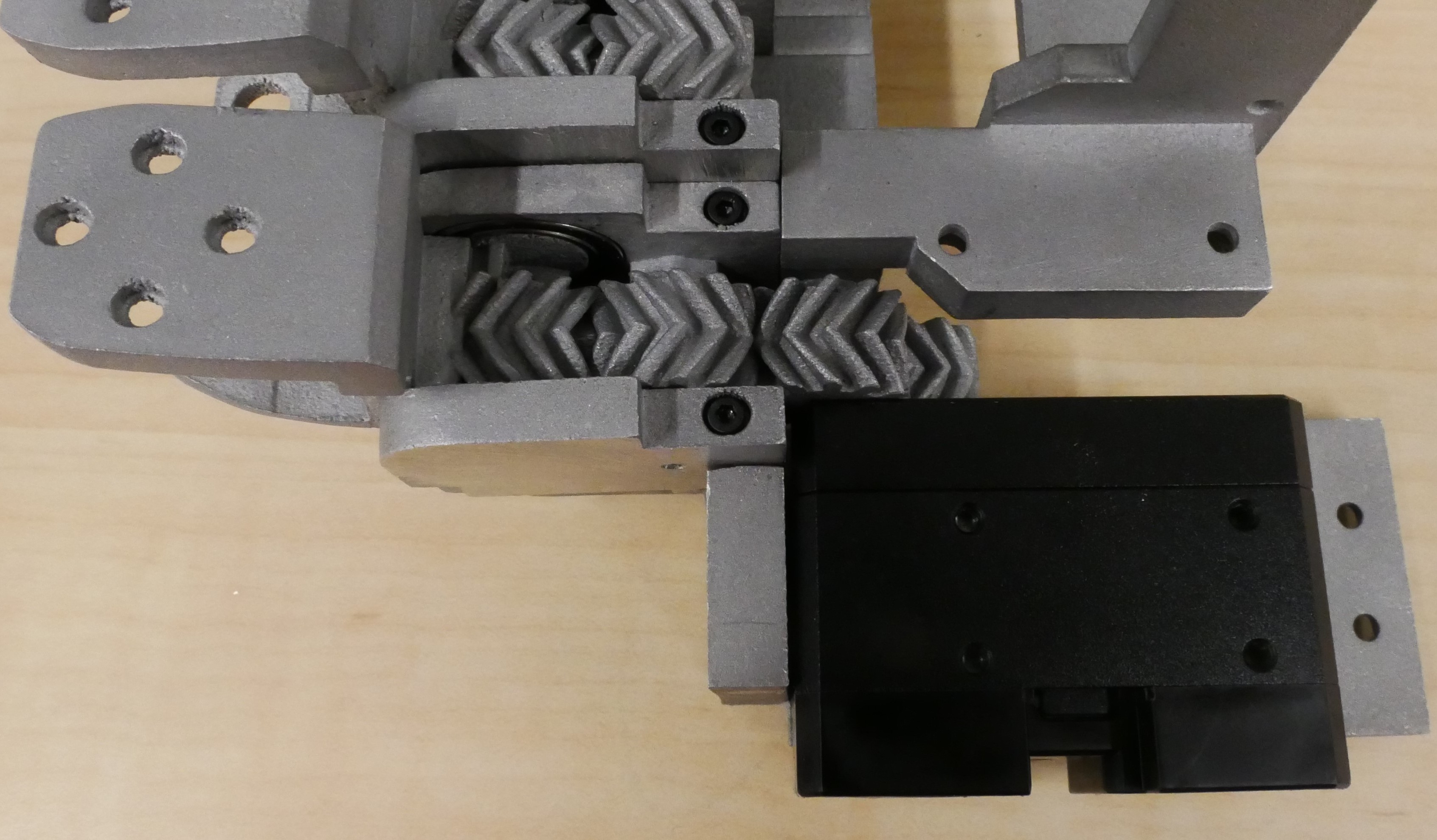
Forming the Palm
Locate one XM430-W210-T motor, one XM430-W350-T motor, and two HN12-I101 sets. Press a HN12-I101 to the back of each motor.
Connecting 4 Fingers Lower to No Fingers Lower
- Identify the central cavity in the No Fingers Lower component and place the XM430-W350-T motor into the cavity.
- Align the motor's screw holes with the designated locations and insert approx 10 M2 6mm screws.
- Locate the Thumb Lower motor mount. Secure this mount to the motor using six M2.5 6mm screws.
Connecting No Fingers Lower to Thumb Lower
- Identify the central cavity in the 4 Fingers Lower component and place the XM430-W210-T motor into the cavity.
- Align the motor's screw holes with the designated locations and insert approx 4 M2 8mm screws into the horn and approx 6 M2 6mm screws into the idler.
- Locate the No Fingers Lower motor mount. Secure this mount to the motor using six M2.5 6mm screws.
Tip: It may be difficult to get all of the screws into the horns and idlers, this is normal. Just make sure the palm feels secure.
Palm Upper on 4 Fingers
- Slot the Palm Upper over the Palm Lower. Attach with two M3 6mm screws.
Palm Upper on No Fingers
- Slot the Palm Upper over the Palm Lower. Attach with two M3 6mm screws.
- Optionally you can also add one M3 6mm brass insert to the inner corner of Upper No fingers and fasten it to the No Fingers Lower using an M3 6mm screw.
Palm Upper on Thumb
- Slot the Palm Upper over the Palm Lower. Attach with two M3 6mm screws.
Tip: The palm upper may feel a bit stiff initially, but this is normal. After being actuated a few times, they will bend and slide over each other with ease.
Mounting and Electronics
- Find at least two M2 6mm brass inserts and a soldering iron.
- Heat the soldering iron to around 240C
- Press the brass inserts into the holes
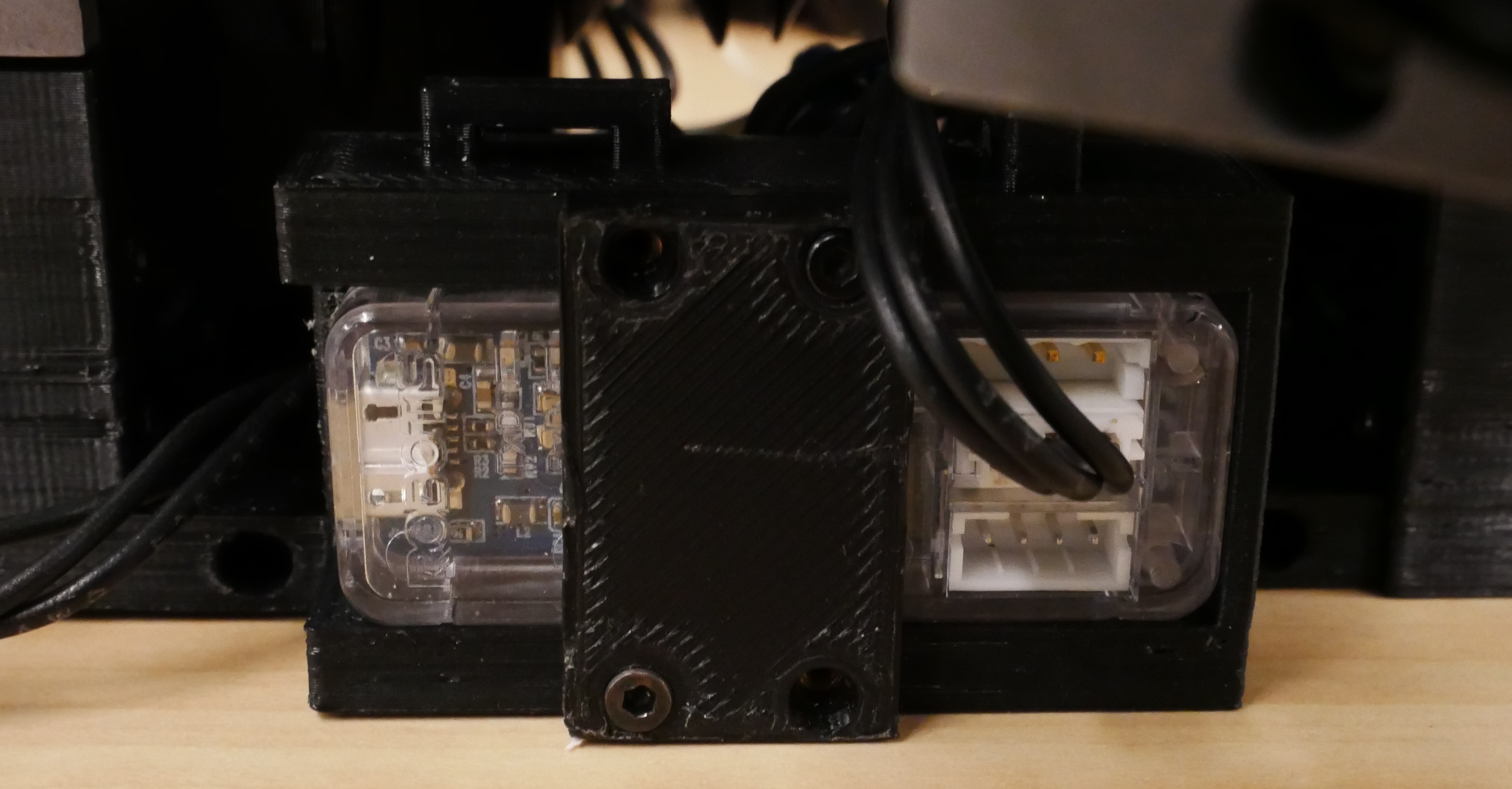
- Place the U2D2 in with the USB port facing out.
- Screw the U2D2 cover over it with M2 6mm screws.
Four Fingers Bottom Mount (recommended):
- Find at least eight M3 6mm brass inserts and a soldering iron.
- Heat the soldering iron to around 240C
- Press the brass inserts into the holes around the bottom perimeter of 4 Fingers Bottom.
- Screw the 4 Fingers Mount onto your preferred arm using M6 screws.
- Use M3 6mm screws on the perimeter of the mount to screw it into 4 Fingers Bottom.
No Fingers Palm Lower Mount:
- Gather at least two M3 6mm brass inserts and a soldering iron.
- Heat the soldering iron to approximately 240°C.
- Carefully press the brass inserts into the designated holes on the top of the No Fingers Mount.
- Secure the mount to the No Fingers Lower Palm using four M3 screws.
- Attach the assembly to your preferred arm using M6 screws.
Tip: While No Fingers Mount is more anatomically correct, it is more prone to breakage and motor strain so I do not recommend it.
Please follow a similar instructions to the LEAP V1 in the setup electronics part of this page. Instead the IDs are as follows:
| ID | MCP Side | MCP Forward | PIP/DIP |
|---|---|---|---|
| Index | 0 | 1 | 2 |
| Middle | 3 | 4 | 5 |
| Ring | 6 | 7 | 8 |
| Pinky | 9 | 10 | 11 |
| Thumb | 12 | 13 | 14 |
| Palm Thumb: 15 | Palm 4 Fingers: 16 | ||
Dynamixel motors are bus-based servos, meaning each motor has a unique ID and they all share a common wiring system (the bus). The connectors on the back of the motors are identical, and the motors are interconnected via these connectors. I recommend using the MCP sides and palm motors as the terminus points for the bus. This results in a total of 7 terminus points for the motors plus 1 for the U2D2. Next, create a central splitter power cable similar to the one used in the LEAP Hand v1, but with 8 connectors extending from it, like an octopus. Then, you can chain the motors out from there using normal cables. This setup will ensure that all motors are connected to each other and to the U2D2.
Warning: Ensure that the MCP Side cables are not pulled out or caught in the gears when the MCP moves up and down, as this could damage the motors. I strongly recommend following the wiring setup shown in the image above.
Congratulations on completing the assembly of the hand!
When powering on the hand for the first time and running the tensioning script, ensure that the tendons are properly wrapped and seated inside the pulley grooves:
- The tendons for the index and pinky fingers should wrap around the pulley towards the front of the hand.
- The tendons for the middle and ring fingers should wrap around the pulley towards the back of the hand.
Tip: If you are having trouble with the fingers curling, check that the tendons are properly on the pulleys and the knots are tied tightly.